How We Assess Surface Condensation & Mould Risk
A guide to our standalone surface-temperature assessment — proving that a junction stays warm enough to avoid condensation and mould, when a building control body, warranty provider or insurer asks for evidence.
19 June 2026 · 5 min read
The risk we're checking for
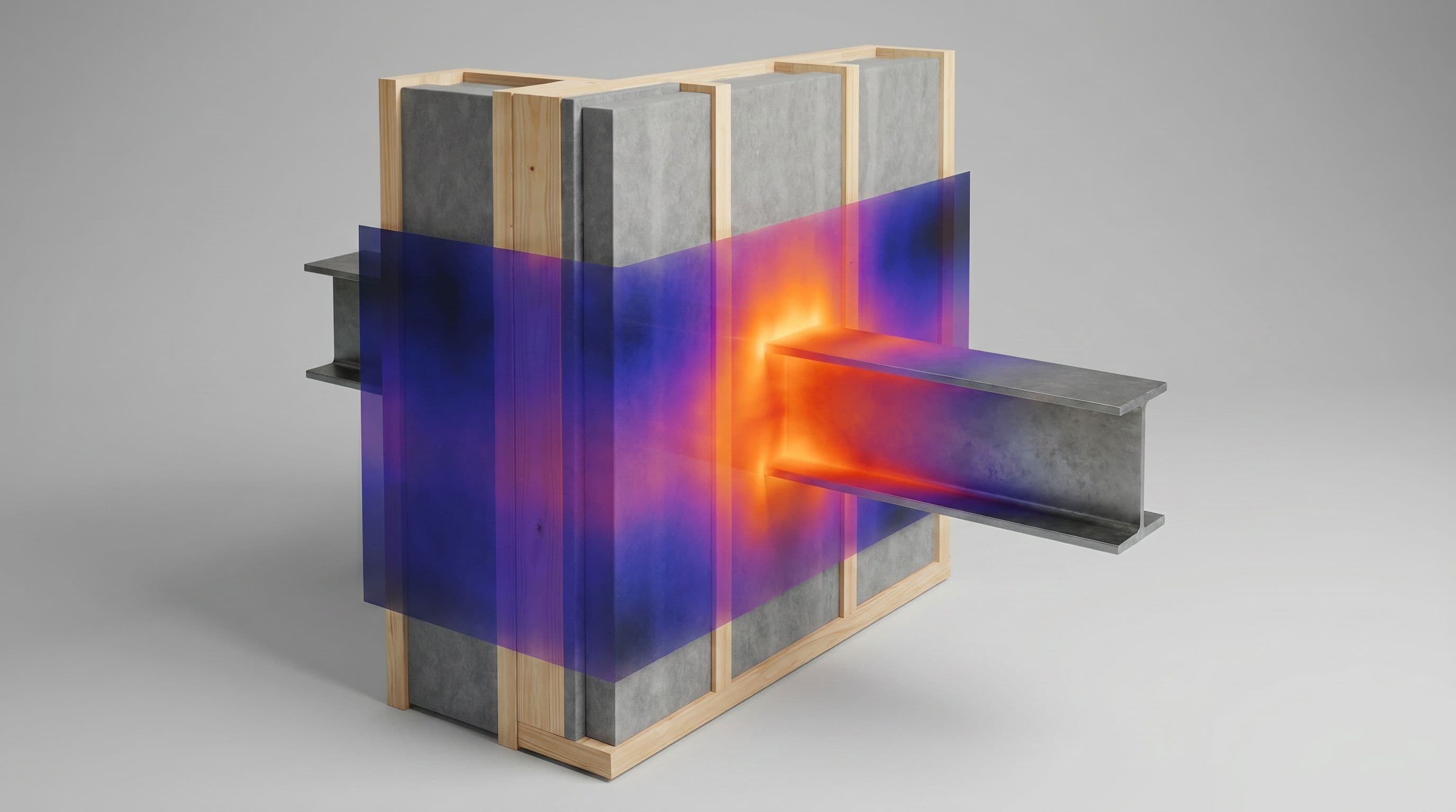
Wherever the internal surface of a wall, floor or roof runs cold, two things can go wrong. If the surface drops below the dew point of the room air, water condenses on it directly. Long before that, once the relative humidity right at the surface stays above 80% for a prolonged time, mould begins to grow — it doesn't need liquid water, just a persistently cool, damp surface. Both show up first at junctions and around openings, in the corners where two cold surfaces meet.
A surface condensation assessment proves, junction by junction, that the coldest point of the detail stays warm enough that the risk of it happening is very low under normal occupancy.
When this is the service you need
The surface-temperature check is already built into our 2D and 3D thermal bridge calculations — every Ψ- or χ-value we report comes with its temperature factor. But sometimes heat loss isn't the question. A building control officer, NHBC or other warranty provider, an insurer or a designer reviewing a tricky detail may simply want confirmation that a specific junction won't condensate or grow mould — without commissioning a full thermal-bridging study.
For that we run the same model as a standalone surface-condensation simulation: we build the geometry in 2D or 3D and solve for the surface-temperature field, but we don't go on to extract the heat-loss coefficients (the Ψ- or χ-values). You get the condensation evidence you've been asked for, faster and at lower cost than a full Ψ-value package, and you can scale up to the heat-loss numbers later if the project comes to need them.
What the assessment gives you
For each junction we report the temperature factor (fRsi):
fRsi = (T<sub>si</sub> − T<sub>e</sub>) / (T<sub>i</sub> − T<sub>e</sub>)
where T<sub>si</sub> is the minimum internal surface temperature anywhere on the detail, and T<sub>i</sub> and T<sub>e</sub> are the internal and external temperatures. Expressing it as a ratio makes it a property of the construction, not of the weather on any one day — the same fRsi describes the junction in a mild week or a cold snap, which is exactly what makes it a reliable design check.
We compare it against the critical temperature factor (fCRsi) for your building type, from BRE IP 1/06. The standard gives these in two tables — one for avoiding mould growth where internal surfaces are absorbent, one for limiting surface condensation where they are not — so the threshold depends on both how moisture-laden the space is and how its surfaces behave:
- 0.75 — dwellings, residential buildings and schools (avoiding mould growth)
- 0.50 — offices and retail premises (limiting surface condensation)
- 0.80 — sports halls, kitchens and canteens
- 0.90 — swimming pools and other high-humidity spaces
Meet the relevant figure and the junction is safe under the assumed occupancy; fall short and the temperature field shows exactly where the cold spot is and what would fix it.
Our method
We model each detail, following the surface-temperature procedure set out in BS EN ISO 10211:
- Build the geometry of the junction — a 2D cross-section for a linear detail, or a full 3D assembly for a three-way corner or penetration — directly from your construction drawings, with every material layer and its thermal conductivity.
- Apply the boundary conditions — the internal and external design temperatures, and the surface resistances appropriate to a surface-temperature check. The internal surface resistance has a strong effect on the result, so it is set to match the convention the assessing body works to: BR 497 (the UK convention) models at the standard BS EN ISO 6946 surface resistances, with the critical temperature factors in IP 1/06 calibrated to that choice; BS EN ISO 13788 instead raises the internal resistance on opaque surfaces to 0.25 m²K/W to represent sheltered corners. We state which we have applied.
- Set the model extent so the cut-off planes sit far enough from the junction that they don't influence the result.
- Refine the mesh until the surface-temperature field stops changing — a mesh-independent, reproducible result, exactly as BR 497 requires.
- Solve the steady-state heat-transfer field and extract the minimum internal surface temperature at the coldest point of the detail, then calculate fRsi. Because the coldest point of a three-way corner is colder than any of the flat sections that form it, corners are assessed in 3D.
- Apply UK conventions from BR 497 throughout — external dimensions, standard resistances and the agreed treatment of junctions — so the result is consistent and audit-ready.
Our models are validated against the benchmark test cases in BS EN ISO 10211, so you can rely on the numbers.
The standards we follow
Core method
- BS EN ISO 10211 — numerical calculation of surface temperatures (and heat flows) at thermal bridges; the 2D/3D modelling method itself.
- BS EN ISO 6946 — thermal resistance of plane building elements and the standard internal/external surface resistances.
Condensation, mould and UK conventions
- BS EN ISO 13788 — how the risk of mould (monthly-mean surface humidity above 80%) and surface condensation is assessed from internal and external climate, and the surface resistances to use.
- BRE IP 1/06 — the critical temperature factors (fCRsi) for avoiding mould growth and limiting surface condensation in UK buildings.
- BR 497 (BRE) — the UK conventions for calculating temperature factors consistently.
- BS EN ISO 13370 — heat transfer through the ground, for floor and below-ground junctions.
Glazing, framing and cladding
- BS EN ISO 10077-1 & -2 — surface temperatures of windows and doors, including 2D modelling of frames where condensation forms on cold glazing edges and spacers.
- BS EN ISO 12631 — thermal performance of curtain walling.
What you receive
A short technical report for each detail: the modelled geometry, a surface-temperature plot showing the coldest point, the temperature factor (fRsi), and a clear pass/fail against the critical value in BRE IP 1/06, with the standards and conventions applied set out in full — everything a building control body, warranty provider or insurer needs to accept that the junction is free of surface-condensation and mould risk.