How We Calculate the P1 Junction (Party Wall to Ground Floor) in 3D
A guide to the SAP junction that can't be captured in a single section — why the party-wall-to-ground-floor junction (P1) needs two full 3D models, and how BR 497 turns them into the Ψ-value your assessment needs.
19 June 2026 · 5 min read
What the P1 junction is
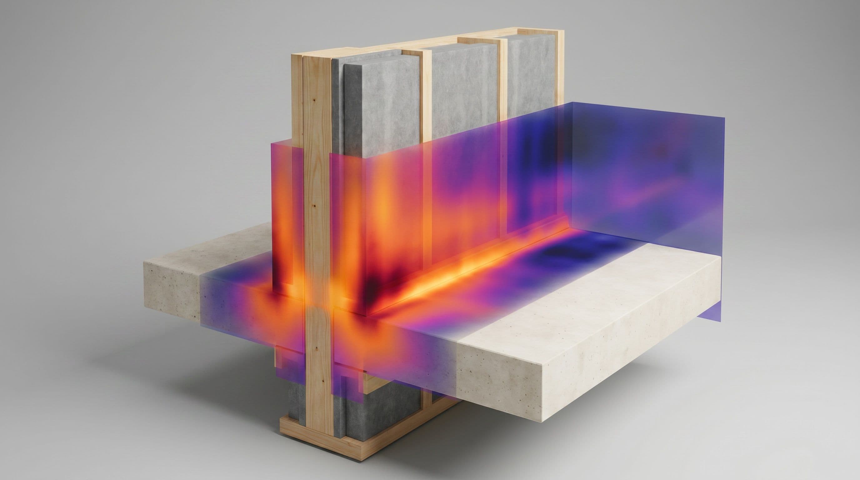
The Standard Assessment Procedure (SAP) lists every junction type in a home in its Table K1, each with a reference code and a linear thermal transmittance (Ψ-value, W/m·K) that adds to the dwelling's heat loss. Most are external-wall details — lintels, sills, eaves, corners — and carry E-codes. The P-codes cover junctions that involve the party (separating) wall, and P1 is the junction where the party wall meets the ground floor.
A party wall separates two heated homes, so very little heat crosses its face. But where it lands on the ground floor it is a different story: the wall and its foundation reach down into cold ground, opening a path for heat to flow out beneath the insulation line and away. That loss is real, it is genuinely three-dimensional, and SAP accounts for it through the P1 junction's Ψ-value.
Why one model isn't enough
For most junctions a single 2D cross-section is all you need, and even the more awkward ones resolve with a single 3D model. P1 is the exception. BR 497 is explicit that these ground-connected junctions "have a complex interaction of heat flows to and through the connecting ground" and that the Ψ-value "cannot be adequately determined from a single model (2D or 3D)" — it has to be extracted from the difference between two 3D models.
The reason is the ground. Heat leaving the foot of the party wall spreads out through a large volume of soil around the foundation before it reaches the outside, and that volume behaves three-dimensionally. You can only isolate the junction's own contribution by modelling the floor twice — once with the party wall and its foundation, once without — and taking the difference. Hence two full 3D models, each carrying a large block of ground.
What the calculation gives you
The linear thermal transmittance (Ψ) of the P1 junction — the extra heat loss per metre where the party wall meets the floor, over and above the plane floor either side. It is built from the two models:
Ψ<sub>c</sub> = (Q<sub>1</sub> − Q<sub>2</sub>) / [(T<sub>i</sub> − T<sub>e</sub>) · L]
where Q<sub>1</sub> is the heat loss with the party wall present, Q<sub>2</sub> the heat loss with it removed and replaced by floor, and L the modelled length of junction. For a wall between two properties a further term is added for the strip of floor the party wall stands on (which the floor U-value never counts): Ψ = Ψ<sub>c</sub> + (t<sub>wall</sub> · U′<sub>f</sub>). Because the wall is shared, half the resulting Ψ-value is assigned to each dwelling.
This Ψ-value feeds the building's transmission heat-loss coefficient in SAP — H<sub>TB</sub> = Σ(l · Ψ) — exactly like any other junction, but now with the ground heat loss properly counted rather than guessed.
Our method
We model the junction in COMSOL Multiphysics, following BR 497 §4.8.1 and the numerical procedure of BS EN ISO 10211:
- Build two identical 3D models of the ground floor and the surrounding ground from your construction drawings — the first with the party wall and its foundation in place, the second with the wall removed and replaced by a continuation of the floor. Everything else is the same.
- Include the ground as a large 3D volume, sized per BS EN ISO 13370. By convention the floor is modelled to its characteristic dimension (taken as 8 m for the standard end-terrace built form), with half the floor represented out to a 4 m adiabatic plane and the party wall 2.4 m tall.
- Replace the external walls with an adiabatic boundary at the edge of the floor, so the Ψ-value reflects only the party-wall/floor junction and not whatever external wall happens to abut it — keeping the result transferable between built forms.
- Apply the boundary conditions — 20 °C inside, 0 °C outside, and the standard surface resistances from BS EN ISO 6946 (0.13 horizontal and 0.17 downward internally, 0.04 externally).
- Solve and subtract — refine the mesh until the heat flows are stable, then take Q<sub>1</sub> and Q<sub>2</sub> from the two models and apply the BR 497 formulae above, including the floor-strip term and the half-share to each dwelling. Solid and suspended ground floors are each handled by their own variant of the convention.
- Apply BR 497 throughout — external dimensions, the agreed ground treatment and surface resistances — so the figure is consistent and audit-ready.
Our models are validated against the benchmark test cases in BS EN ISO 10211 and reproduce the BR 497 worked example for this junction, so you can rely on the numbers.
The standards we follow
Core method
- BR 497 (BRE) — §4.8.1 sets out the UK convention for the party-wall/ground-floor junction: the two-model method, the ground treatment and the split between dwellings. This is the definition of the P1 calculation.
- BS EN ISO 10211 — the numerical calculation of 3D heat flows that both models rely on.
- BS EN ISO 13370 — heat transfer through the ground, which governs the size and treatment of the soil volume.
- BS EN ISO 6946 — U-values of the plane floor and walls, and the standard surface resistances.
Compliance and companion checks
- SAP (Table K1) — the source of the P1 reference and where the Ψ-value is entered into the dwelling's heat-loss assessment and Part L compliance.
- BRE IP 1/06 & BS EN ISO 13788 — the temperature-factor check for surface condensation and mould, available from the same model where the junction's coldest point is a concern.
What you receive
A short technical report for the junction: the geometry of both 3D models and the ground they include, the conductivities and boundary conditions used, the two heat flows and the derived P1 Ψ-value — with the half-value assigned to each dwelling clearly stated — and the standards and conventions applied in full, so a SAP assessor or building control body can accept the figure as proven for the dwelling rather than taken from a default.