How We Calculate 3D U-values for Rainscreen & SFS Facades
A guide to our method for build-ups where metal brackets, rails and steel studs pierce the insulation — why a hand-calculated U-value overstates their performance, and how we model the repeating bridge in 3D to get the figure that counts.
19 June 2026 · 6 min read
Why these walls need a 3D U-value
A U-value (W/m²K) is the rate of heat loss through one square metre of a wall for each degree of temperature difference across it. For a simple layered wall you can work it out by hand, adding up the thermal resistance of each layer. But modern facades rarely stay simple — the insulation is pierced, again and again, by metal:
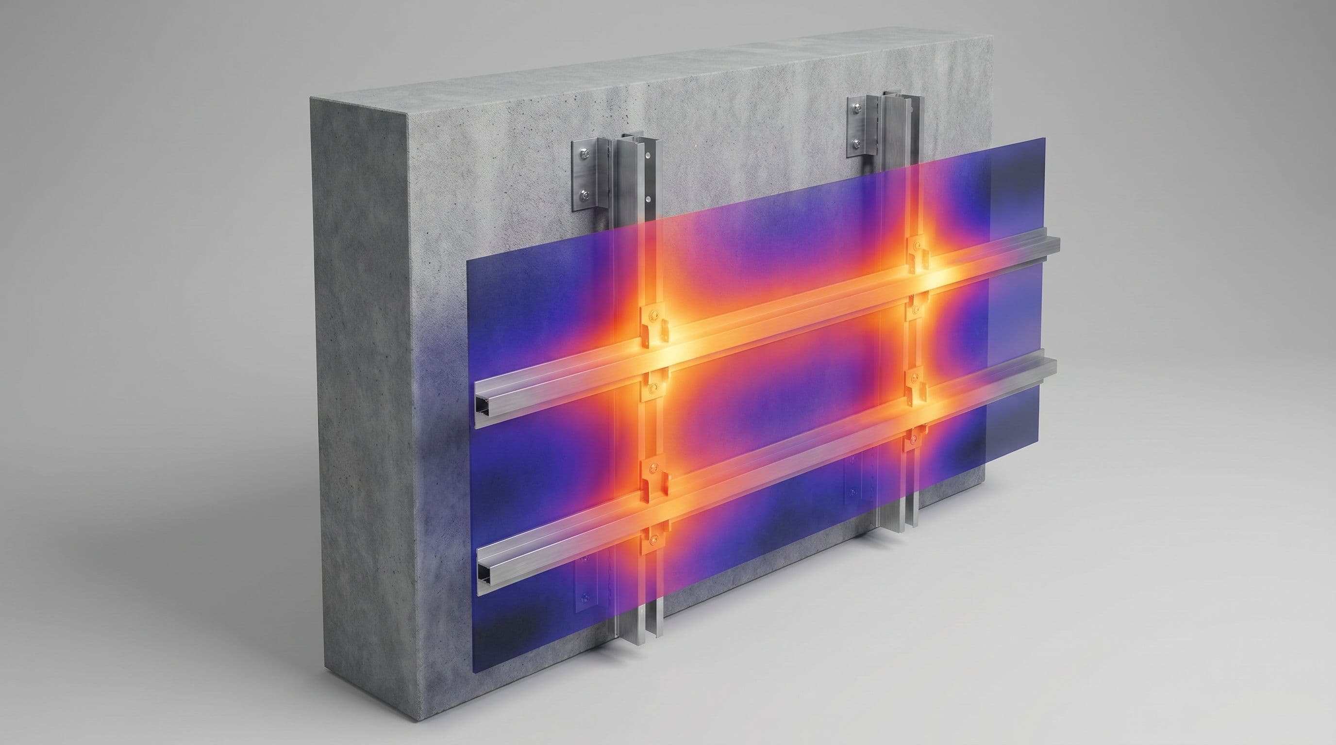
- Rainscreen cladding hangs off helping-hand brackets and carrier rails that reach back through the insulation to the structure.
- SFS (steel-framing system) infill walls are built on a grid of light-gauge steel studs spanning the insulated zone.
- Wall ties and other point fixings do the same on a smaller scale.
Steel conducts heat hundreds of times faster than insulation, so every one of these is a thermal bridge that short-circuits the insulation layer. A hand calculation — even the combined (upper–lower limit) method of BS EN ISO 6946 — cannot represent this: that method is explicitly not valid where insulation is bridged by metal. Ignore the bridges and the U-value you report is optimistic, sometimes badly so, and the wall as built loses far more heat than the layers suggest. The only reliable way to get the real figure is to model the bridge in three dimensions.
Why it has to be 3D — and why spacing matters
A bracket is a point feature and a stud is interrupted along its length, so a flat 2D section can't represent either. As soon as a bracket or a profiled rail is present, the internal surface temperature varies across the wall and the simple U-value formula stops applying — a full 3D model is the only option.
The bridges also repeat on a grid, and how densely they repeat changes everything. Brackets might sit at 600 mm along rails that are themselves at 1200–1800 mm centres; SFS studs are typically at 400 or 600 mm. We model one representative unit cell — the smallest tile that, repeated, rebuilds the whole facade — sized to the actual fixing grid and stud spacing. Get the cell size wrong and the result is wrong: too small a tile over-counts the metal and overstates the U-value, too large under-counts it. The spacings you give us are part of the answer, not a detail.
What the calculation gives you
For each build-up we report the effective (whole-wall) U-value — the U-value of the construction as it really performs, with every bracket, rail and stud included. It comes directly from the heat flow through the unit-cell model:
U = Q / [(T<sub>i</sub> − T<sub>e</sub>) · A]
where Q is the heat flow through the cell, T<sub>i</sub> − T<sub>e</sub> is the inside-to-outside temperature difference, and A is the cell's face area. Where it's more useful, we can instead report the plain U-value plus the point thermal transmittance (χ, W/K) of each fixing and the linear transmittance (Ψ, W/m·K) of each rail or stud run — the two forms give the same total heat loss, and BS EN ISO 6946 builds its own fastener correction the same way.
This effective U-value is the figure that belongs in the building's energy assessment (SAP/SBEM) and its Part L / Building Regulations compliance, and the one a facade engineer needs to confirm the wall hits its target. As a by-product the same model gives the internal surface temperature at the coldest fixing, so we can also confirm there's no surface-condensation or mould risk — see our note on surface condensation assessments.
Our method
We model each build-up in COMSOL Multiphysics, following BS EN ISO 10211 and the metal-cladding conventions of MCRMA TP18:
- Build the unit cell in 3D from your construction drawings and the fixing schedule — every layer with its measured thermal conductivity, and the bracket, rail and stud geometry exactly as specified.
- Size the cell to the real spacing — the bracket grid and stud centres — so it carries the correct amount of metal per square metre. It is the repeating tile of the facade, no smaller and no larger; sizing it wrong is the single biggest source of error in these calculations.
- Apply the boundary conditions — internal and external design temperatures and the standard surface resistances from BS EN ISO 6946 — with adiabatic (mirror) planes on the four sides of the cell, the correct treatment for a repeating element.
- Refine the mesh around the metal/insulation interfaces, where the heat path turns sharply, until the result is stable — TP18's test is successive refinements agreeing to within 2% on heat flow and 0.1 °C on surface temperature.
- Solve the steady-state heat-transfer field, take the total heat flow Q through the cell, then divide by the temperature difference and cell area to give the effective U-value (and, if wanted, the χ- and Ψ-contributions of the fixings).
- List every conductivity used alongside the result and apply the UK conventions of BR 497 throughout, so the figure is transparent and audit-ready.
Our models are validated against the benchmark test cases in BS EN ISO 10211, so you can rely on the numbers.
The standards we follow
Core method
- BS EN ISO 6946 — the U-value of plane building elements, the standard surface resistances, and the fastener and air-gap corrections; it is also the standard that rules its own simplified method out where insulation is bridged by metal.
- BS EN ISO 10211 — numerical calculation of heat flows in 2D and 3D, used to model the bridge and derive the point and linear transmittances.
Metal cladding and UK conventions
- MCRMA TP18 — conventions for U-, f- and Ψ-values of metal cladding, rainscreen and rail-and-bracket systems using 2D and 3D models, including how large the model must be to represent the fixing grid faithfully.
- BR 497 (BRE) — the UK conventions for consistent, comparable and auditable results.
Surface temperature and ground
- BRE IP 1/06 & BS EN ISO 13788 — the temperature-factor check for surface condensation and mould at the coldest fixing.
- BS EN ISO 13370 — heat transfer through the ground, where the facade meets the floor or runs below ground.
Glazing and curtain walling
- BS EN ISO 10077-1 & -2 — thermal transmittance of windows and doors, for framed openings within the facade.
- BS EN ISO 12631 — thermal transmittance of curtain walling, where transoms and mullions form the repeating bridge.
What you receive
A short technical report for each build-up: the modelled unit cell and the fixing grid it represents, the conductivities used, the effective U-value (with the χ- and Ψ-breakdown where useful), the surface temperature at the coldest fixing, and a clear statement of the standards and conventions applied — everything a facade engineer, building control body or energy assessor needs to take the U-value as proven for the wall as it will actually be built.