How We Calculate 2D Thermal Bridges
A guide to our method for assessing linear thermal bridges — the heat lost at junctions, the risk of condensation, and the standards behind every figure we report.
19 June 2026 · 3 min read
Why thermal bridges matter
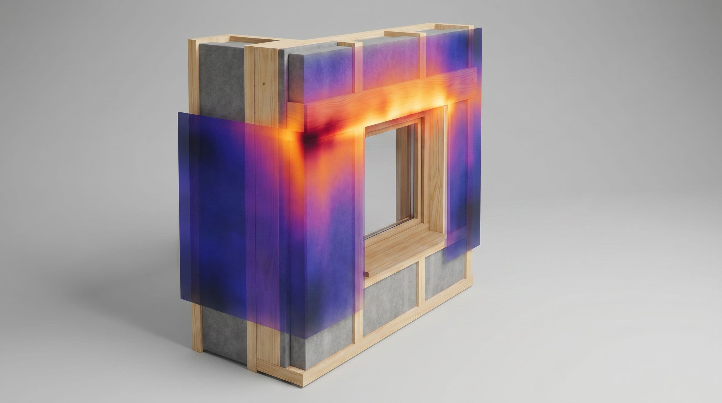
A thermal bridge is any part of the building envelope where heat escapes more easily than through the surrounding wall, roof or floor — typically at junctions, around openings, and wherever a more conductive material breaks the insulation. They do two things you care about: they add to the building's heat loss, and they cool the internal surface enough to risk surface condensation and mould growth in the corners where the two meet.
A 2D thermal bridge calculation quantifies both, so the detail can be designed out before it reaches site.
What the calculation gives you
For each junction we report two numbers:
- Linear thermal transmittance (Ψ-value, W/m·K) — the extra heat loss along one metre of the junction, over and above the plain wall and floor either side. These Ψ-values feed directly into the building's energy assessment (SAP/SBEM) and Building Regulations compliance.
- Temperature factor (fRsi) — a measure of how cold the internal surface gets at the junction, independent of the weather. It is checked against the critical value in BRE IP 1/06: 0.75 for dwellings, schools and residential buildings (higher for humid spaces such as pools). Meet it, and the detail is safe from mould under normal occupancy.
Our method
We model each detail in COMSOL Multiphysics, following the procedure set out in BS EN ISO 10211:
- Build the cross-section of the junction directly from your construction drawings, with every material layer and its measured thermal conductivity.
- Apply the boundary conditions — internal and external temperatures, and the standard surface resistances from BS EN ISO 6946.
- Set the model extent so the cut-off planes sit far enough from the junction that they don't influence the result.
- Refine the mesh until the heat flow and surface temperature stop changing — a mesh-independent, reproducible result, exactly as BR 497 requires.
- Solve the steady-state heat-transfer field, then extract the heat flow to derive the Ψ-value and the minimum internal surface temperature to derive fRsi.
- Apply UK conventions from BR 497 throughout — external dimensions, standard resistances and the agreed treatment of ground-floor junctions — so the figures are consistent and audit-ready.
Our models are validated against the benchmark test cases in BS EN ISO 10211, so you can rely on the numbers.
The standards we follow
Core method
- BS EN ISO 10211 — numerical calculation of heat flows and surface temperatures at thermal bridges (the 2D/3D modelling method itself).
- BS EN ISO 6946 — thermal resistance of plane building elements and the standard internal/external surface resistances.
UK conventions
- BR 497 (BRE) — the UK conventions for calculating Ψ-values and temperature factors consistently.
- BRE IP 1/06 — critical temperature factors for avoiding mould, and how junction heat loss carries into Building Regulations.
Condensation and ground heat loss
- BS EN ISO 13788 — assessing surface and interstitial condensation risk.
- BS EN ISO 13370 — heat transfer through the ground, for floor and below-ground junctions.
Glazing, framing and cladding
- BS EN ISO 10077-1 & -2 — thermal transmittance of windows and doors, including 2D modelling of frames.
- BS EN ISO 12631 — thermal transmittance of curtain walling.
- MCRMA TP18 — conventions for U-, f- and Ψ-values of metal cladding systems.
What you receive
A short technical report for each detail: the modelled geometry, the Ψ-value and temperature factor, a pass/fail against the relevant critical value, and a clear statement of the standards and conventions applied — everything a building control body or certifier needs to accept the result.